Subscribe to:
Posts
(
Atom
)
Featured post
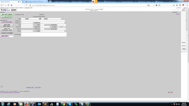
Vicidial With WebRTC
Vicidial With WebRTC VICIDial is well known open source call center software. It has been in use by many small to large scaled con...